


In our wireless world the need of RF component testing is one of a key factors to bring a product to market. Devices are getting smaller and are containing more and more complex components. It is a must to have knowledge of complex impedance (or admittance) and reflection / transmission parameters to bring the most optimum functionality to the RF device. RF components like filters, resonators, etc. can be calculated according to capacitance and inductive values. Software simulators can take these values and help fine tune the design. But at the end of the day, the quality and performance needs to be measured. For several applications, a scalar network analyzer might be adequate but for some specific design work phase information is required. A vector network analyzer [VNA] has the possibility to measure amplitude and phase over specified frequency range.
The vector network analysis allows for the measurement of complex scattering parameter [Sxx] of a device under test [DUT] over a specified frequency range. Vector network analysis allows for the characterization of a scattered matrix with reflection [S11] and transmission [S21] factors. These parameters are required to design e.g. a matching circuit for an amplifier. With phase information it is also possible to calculate the time range where additional failures at different positions can be analyzed. Due to the complex (vector) characteristic it possible to make an accurate correction with calibration routines.
RIGOL's VNA solution in RSA5000N and RSA3000N [RSAxN] series can perform three different measurements these include reflection [S11], transmission [S21] and Distance-To-Fault [DTF] measurements. All three of these measurements have several different views which allows engineers to easily determine a DUT's frequency response, phase, SWR, Smith Charts and Polar Plane measurements. In figure 1 the principle of S-Parameter measurement is visible. These parameters can be calculated with the complex factors ax and bx. For example, a1 refers to the incident wave into the DUT and b1 refers to the reflected wave. The transmitted factor after DUT is referring to b2. At RSAxN version an incident wave can only be generated by port 1. Therefore, a2 is 0.
The principle of S Parameter Measurement in a network:
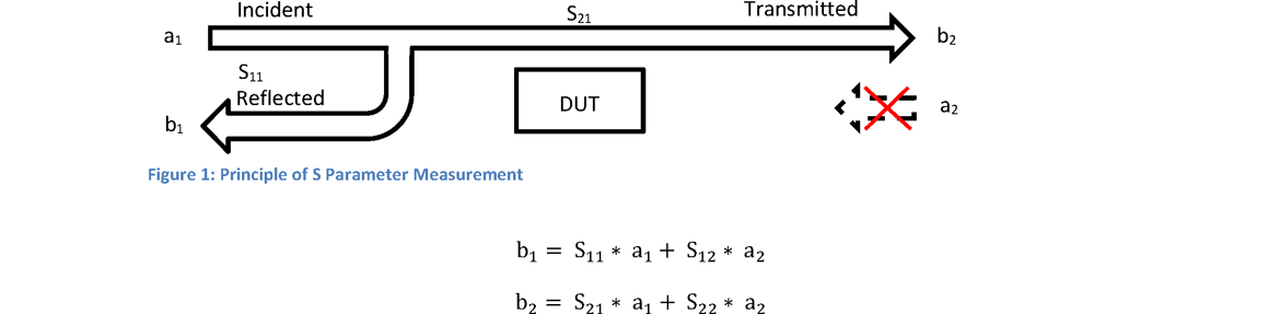


 Figure 2: Smith Chard Overview in Impedance area referring to 50 ω (Click image to enlarge)
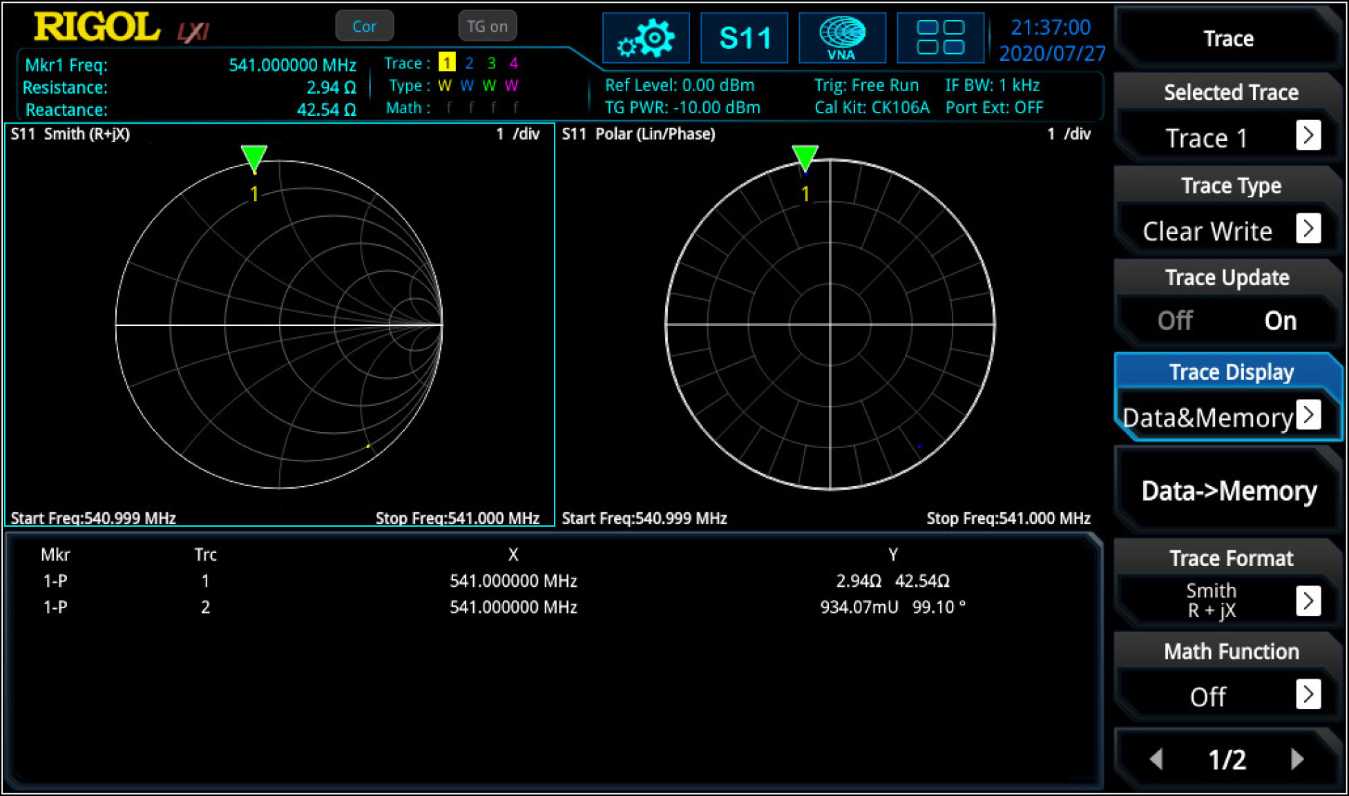 Figure 3: Series connection with capacity and resistance without a line (first dot) and with a line of 16 cm in between @541 MHz (Click image to enlarge)
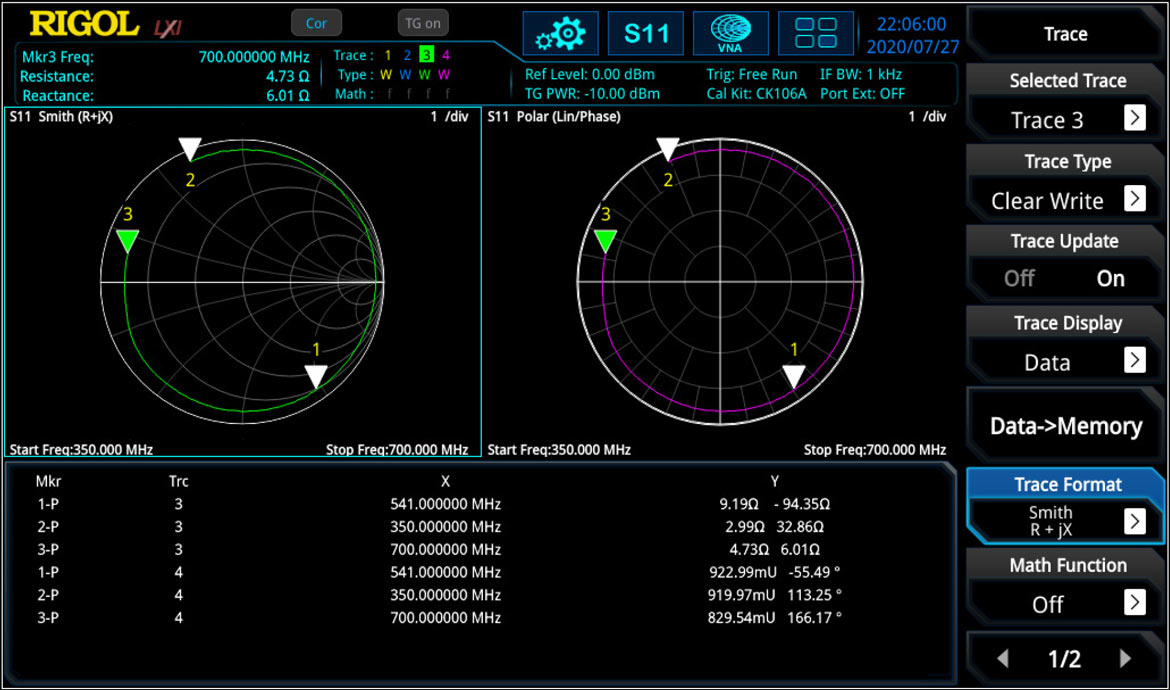 Figure 4: Frequency response curve - frequency is increasing clockwise (Click image to enlarge)

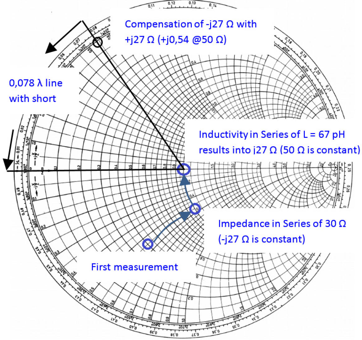

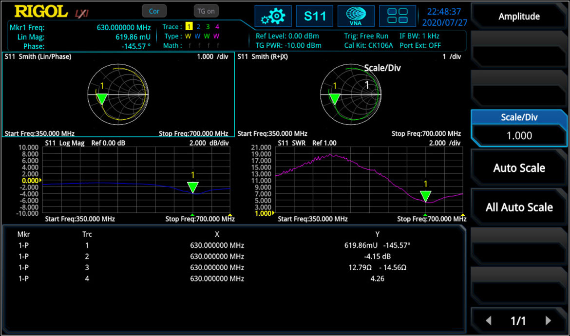 Figure 6: Different window of S11 parameter like smith- and Polar Plane, logarithm. Magnitude and SWR (Click images to enlarge)
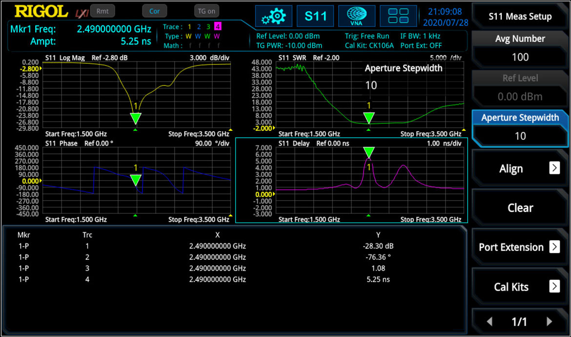 Figure 7: S11 measurement: logarithmic magnitude of |r|; phase over-, SWR over- and group delay over frequency (Click images to enlarge)

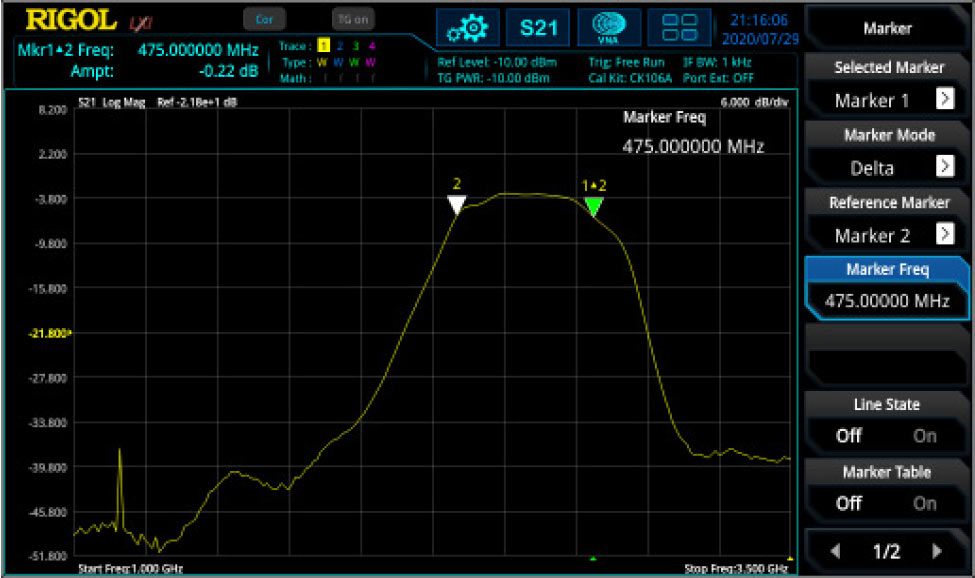
 Figure 9: S21 measurement with insertion loss (green), phase (blue) and group delay (pink) (Click images to enlarge)
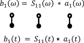

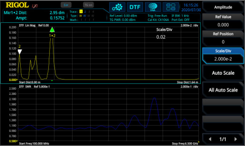
 Figure 11: Error Model of One Port Measurement

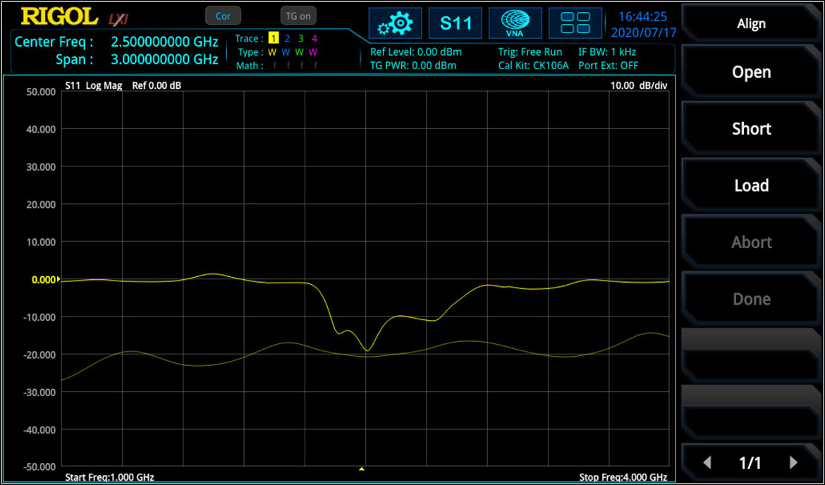 Figure 12: S11 measurement of a band pass filter: Before (thin trace) and after (thick trace) one port calibration (Click images to enlarge)